Select a Catagory:
Breaking News
This area does not yet contain any content.

Entries in Demos (27)

Thursday
Mar192015

Converting a Computer (ATX) Power Supply into a Power Supply You Can Use in Lab

Many PC desktop computers use a power supply known as ATX http://en.wikipedia.org/wiki/ATX . These computer power supplies are surprisingly well made, nearly bulletproof, since computer components are notorious for being easily damaged by getting voltages over or under what they are expecting. Manufacturers go to great lengths to make them durable and close to specs.

And the specs are often fantastic. Most can supply 3.3 V up to 10 A, 5 V up to 20 A, and 12 V up to 10 A. Most have several output wires, so you could have several students use the same supply as long as they together stayed under the current limits. Best of all, most will automatically turn themselves off if your circuit tries to draw too much current. Unplug the power supply, wait 30 seconds or so, and plug it back in, and the supply will be as good as new. No more replacing fuses!

Since power supplies rarely go bad in home computers and they are easy to extract, you can have a ready source of power supplies for more or less free. Surplus houses often sell them for only a few bucks each, if you’d like to go for new.

Their only real downside is that they don’t supply variable current, only fixed levels, but if 3.3 V, 5 V, and 12 V work for you, then they are great.

Materials

  • ATX power supply
  • IEC power cord
  • scissors
  • soldering iron
  • solder
  • electrical tape or shrink wrap
  • wire stripper
  • two incandescent holiday lights
  • four alligator clips with vinyl jackets

Assembly
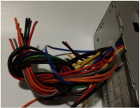
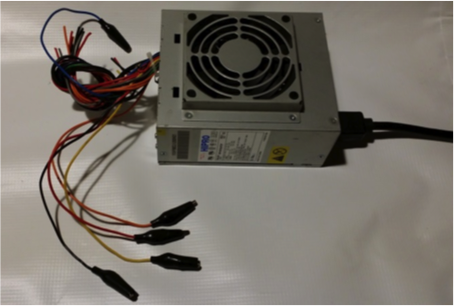
  1. Cut off the connectors from the ends of the power supply using a pair of scissors. Leave the wires long, though. You can tie them into a knot to keep them out of the way.
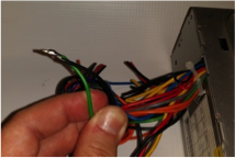


  2. Find the green wire (there is usually only one) and a black wire (there are usually several). Strip the black and green wires and solder together. When the green wire is connected to ground – say by pressing a button – that signals the power supply to turn on. While you could connect a switch to the supply here, it is easier to turn it on permanently and turn it off by unplugging it.
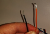


  3. Some power supplies will not turn on unless they are powering something. That is, if nothing is connected to the wires, it won’t start. To solve that problem (and as bonus give a telltale that the power supply is working), strip the ends from two incandescent holiday lights and an orange wire and a black wire.
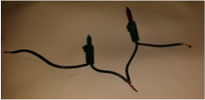


  4. Solder the two incandescent bulbs together in series.
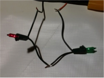


  5. Solder the pair to the orange black wires. Cover the connections with electrical tape or shrink wrap. 
  6. Strip one orange, one red, one yellow, and one black wire.


  7. Solder an alligator clip to each wire. Remember to slide the jacket up the wire BEFORE soldering the wire to the clip. Hold the clip and wiggle the jacket over the clip.
  8. If you’d like, you can strip another set of black, orange, red, and yellow wires and solder on alligator clips. Most supplies can give enough current to run two stations. However, the wires are shortish this way, and if one group draws too much current, both groups will be shut off.

Colors

  • Orange to black = 3.3 V
  • Red to black = 5 V
  • Yellow to black = 12 V
Thursday
Aug082013

LEDs Demonstrate Quantum Mechanics

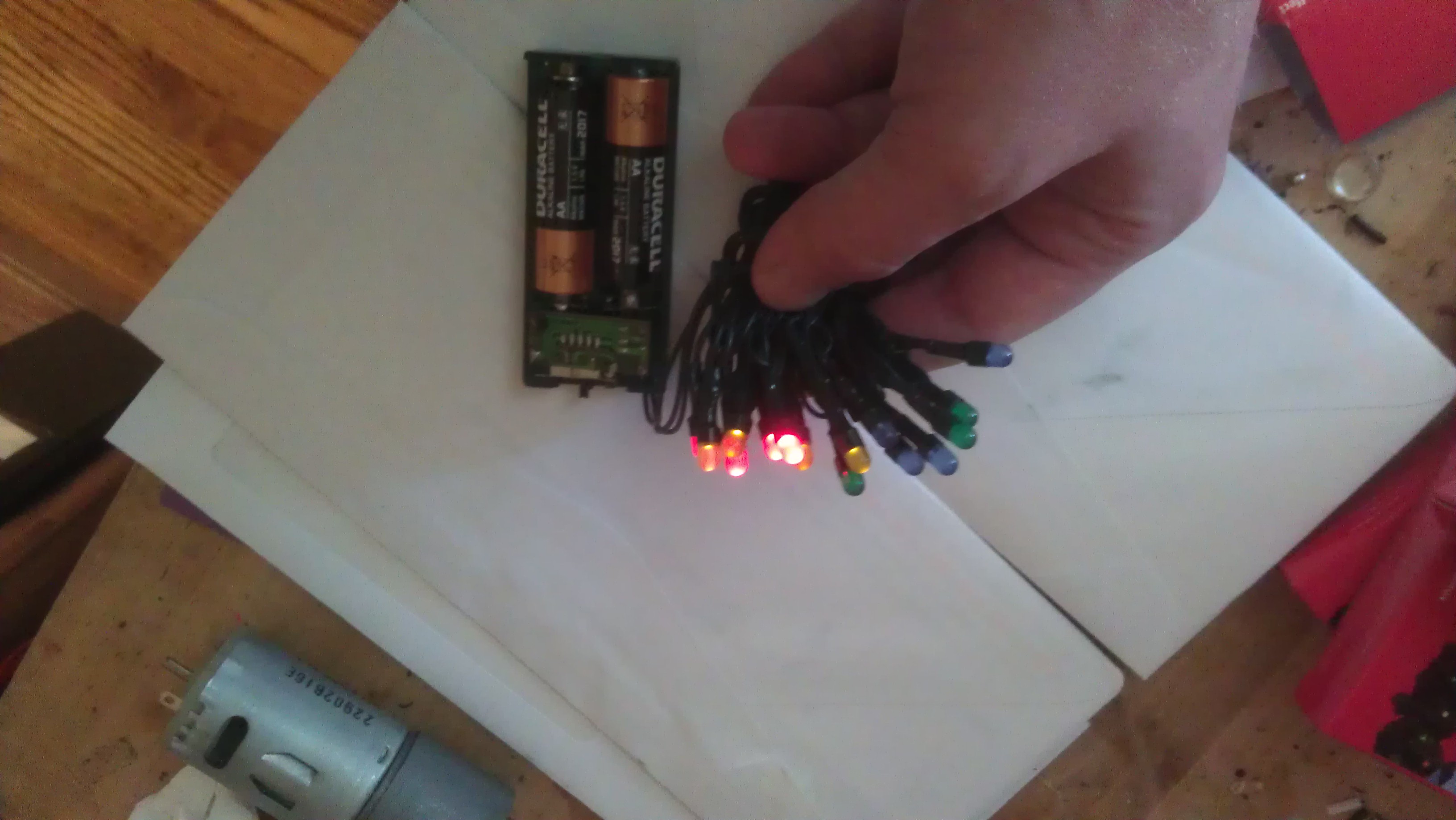
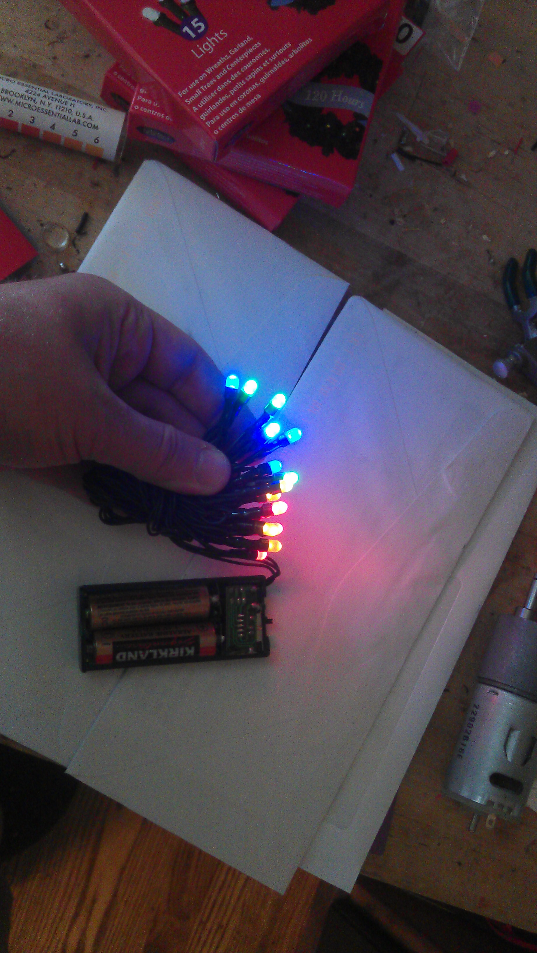
This is a strip of battery-powered LED Christmas Lights which are usually available at Walgreens at Christmas. I got them out to work on a project, turned them on, and was struck by something odd. I used to buy these by the bucket at the low price of three packs for $10 because it was a cheap way to get fairly bright LEDs that were already shrinkwrapped and easy to use. They've changed the lens design to spread out the light more, but they can still be useful. However, that's not what I'm interested in now.

Notice that the red LEDs are really bright, the yellows are dim and the rest are off. This suprised me and made be take a moment to consider what was going on and come up with an explanation.

A clue is that the batteries are mostly used up and aren't able to provide as much voltage as when they were fresh.

LEDs are weird beasts. Like filament light bulbs, if electrons get pushed through them, they start to glow, but unlike filament light bulbs, each color takes a minimum voltage before it will glow. Less than that voltage, you get nothing.

You might wonder why that is. Alhtough the story is really more complicated than this, essentially the LED turns the energy in one of those moving electrons into a bit of light. The energy that an electron has is related to its voltage.

And the energy of light is related to its frequency. The red part of the spectrum has the lowest frequencies and the violet part of the spectrum has the highest frequencies.

So low voltage electrons have low energy and can only make low energy light which is light with low frequencies which is red light. It takes higher energy electrons to make green and blue light. Since there aren't any high energy electrons, the green and blue LEDs can't make any light.

Perhaps you could put two electrons together to make blue light? That doesn't work in most cases, though. Quantum means more or less "the smallest possible amount."

With fresh batteries, everything started to work as you'd expect.


Friday
May042012

Mini-Marshmallow Launcher

because "gun" sounds so violent.

This is a pump action device. The mini-marshmallow is placed in front fo the 1/2 inch pipe. The bottom pipe is pulled out, and the marshmallows get pushed by the outside air pressure (sucked, if you will) deep into the 1/2 inch pipe. The bottom pipe is then forced back in, and the marshmallows are launched forward.

Parts:

  • 2 feet 1/2-inch PVC (schedule 40 or 80) pipe
  • 2 feet 2-inch PVC (schedule 40 or 80) pipe
  • 2 feet 1 1/2 inch PVC (schedule 40 or 80) pipe
  • 2 inch PVC connector sleave
  • 2 inch to 1/2 inch adapter
  • 2 1/2-inch right angle threaded bend
  • small disk of cardboard
  • duct tape
  • 5 inches of thread
  • yarn
  • glue
  • PVC cement
  • mini-marshmallows

Construction


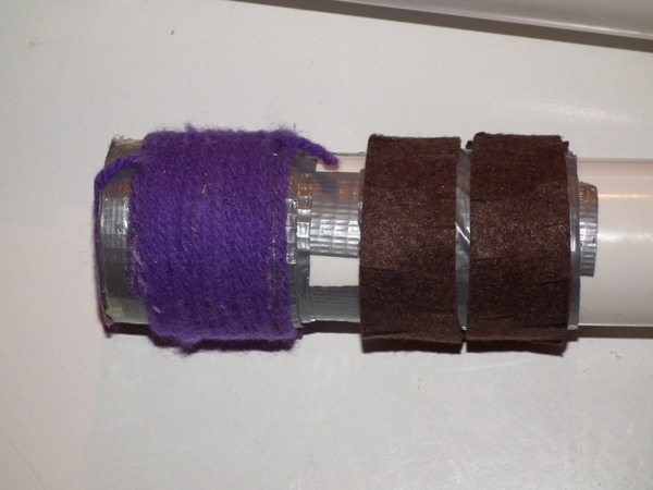
  1. Cut out a piece of cardboard that is the same size as the 1 1/2 inch PVC's cross section. Use duct tape to firmly affix it to the end of the pipe. Wrap duct tape around the end until it is almost the same diameter as the 2 inch pipe. Apply glue to the tape (I used Gorilla Glue) and then wrap with yarn. It should make a snug fit into the pipe. Do the same a bit farther down. Repeat with yarn or use some self adhesive felt. I made snips in alternating sides so that it would lie flatter. Allow to dry.
  2. Dry fit the PVC pipes together using the model above. The small right angle fittings also come in slip fitting rather than thread. I prefer the thread because then I can take it apart.
  3. Place the thread across the 1/2 inch pipe between it and the right angle fitting to make sure that mini-marshmallows can't go all the way into the bent sections.
  4. Once everything is working, use PVC cement to connect the joints.

I didn't come up with this design, I first saw it here. I just adopted it from Nerf darts to mini-marshmallows.

Thursday
May032012

Pressure Cooker Squished Cups

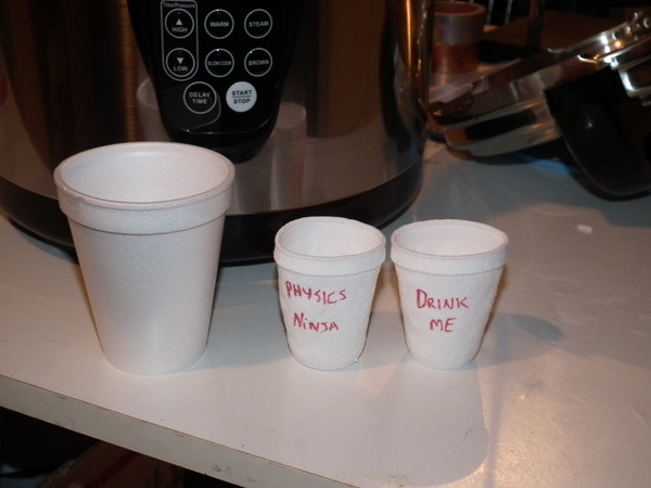
If you put expanded polystyrene (Styrofoam) cups in a pressure cooker and turn up the heat, they will shrink down to approximately 1/6 their original volume.

Procedure

As I'll explain later, you don't actually need a pressure cooker, though they work the best. I use an electric pressure cooker for the show since it is easier to use. I don't need a hot plate, and the countdown timer shuts itself off, but a stove top one works too.

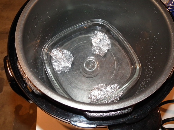
Even gentle heating is important if you want the cups to keep their shape while shrinking. So, you want the cups out of the water,  and on a flat surface that can take the heat but not conduct it too well to the cups. I use a Pyrex lid to a oven casserole. I lift it out of the water with three crumpled balls of aluminum foil.


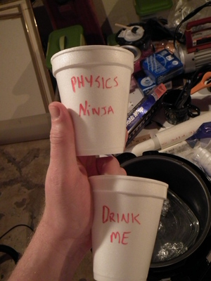
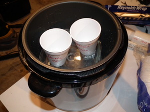
Use permanent marker to write on the cups and place them in the pressure cooker. My cooker takes about 20 minutes at pressure to shrink the cups. You can crowd them in the container. They'll stick a little after you're done, but they easily pull apart.

How Does This Work?

A digression for a moment. When submersibles go down into the depths of the ocean, they often bring Styrofoam with them on the outside of the craft. It gets crushed, like in this picture from some cups taken down in the Alvin.

Does the pressure cooker do the same thing? The pressure cooker "only" has twice the pressure as usual. While that is enough to make a dangerous mess if the cooker were to rupture, that's not high compared to what the Alvin does. Two atmospheres is like going down to a depth of 10 meters. The cups get fully crushed on the Alvin at 300 m. Hmmm....

Perhaps it is the heat? Heat makes the Styrofoam soft and bendy. I'm imagining that the heat (and pressure) pops the foam, and the foam collapses back into its unexpanded state.


Thursday
May032012

Siphon Model

A siphon is usually presented a tube that has one end higher than the other and is completely filled with liquid. A Google image search gives dozens of pictures along that line. 

The explanation that often goes with these pictures has to do with atmospheric pressure. That air pressure is slightly higher on the high side (A) and slightly lower on the down side (B). That's true but not the whole story. The difference in air pressure helps to hold the water together and does push it, but a siphon will work without air pressure. 

A better way to think of a siphon is probably good ol' conservation of energy. Though it takes energy to lift the water over the lip (from A to C) of the first side, the energy can be gained can be returned if the water on the other side ends up lower than where it started in the first side. 

The hard part is actually getting the energy back to the first side to lift the next bit of water. Atmospheric pressure helps to hold the water together so it doesn't break into two pieces at the bend. 

If the material can hold together on its own, then the siphon could work in a vacuum. The beaded chain in my video demonstrates this idea. If you pull it over the top and let it hang to the table it. 

Tuesday
May012012

Improved Elihu Thomson Coil (Jumping Ring)

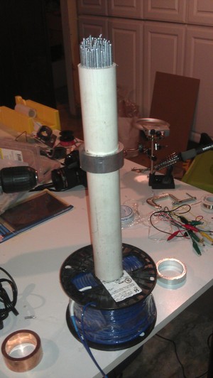
My previous Elihu Thomson (I'm pretty sure that it isn't "Thompson") Coil -- worked okay, but my new one works like a dream, though it is a bit expensive to make, mostly because copper costs so much these days.

Parts:

  • 500 ft spool of stranded (if you can find it) 12 or 14 gauge copper single conductor wire like this
  • sacrificial extension cord
  • heat shrink
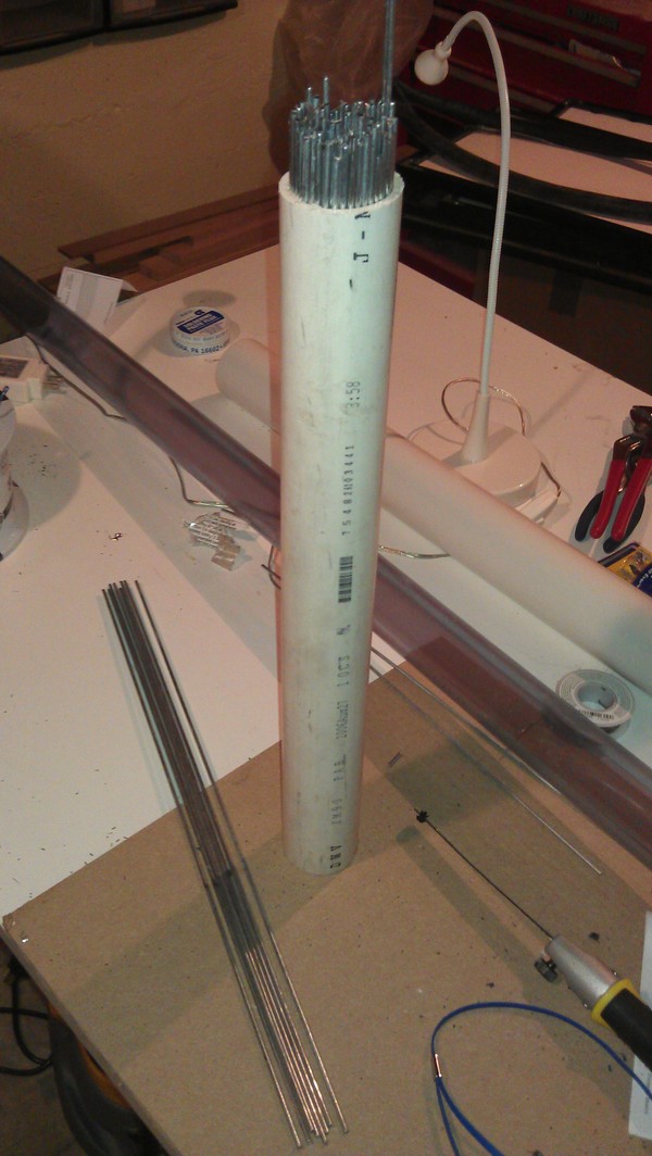
  • 1 1/2 inch schedule 40 or 80 PVC pipe (about 14 inches long)
  • drop ceiling wire or iron welding rods (you are looking for thin iron or mild steel wires at least as long as you PVC pipe) I needed about 100 feet
  • lever action mini bolt cutters like one of these
  • polyurethane spray
  • aluminum and copper rings (see below)

Step 1: Find the right spool of copper wire


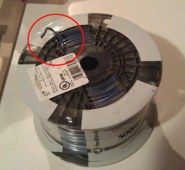
When the manufacturer coils a spool of wire, sometimes they tuck one end of the wire through a gap in the spool towards the center. This is called the tail, and you want to buy a spool that has this. I've outlined it in red. Most do, but you'll need to check. Sometimes it is tucked into the center of the spool; that will work but it's less convenient. 

Step 2: Expanding the hole.

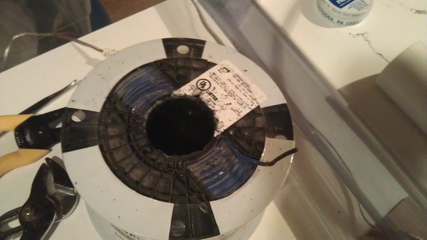
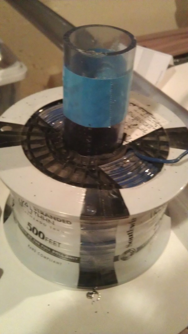
The spool will have a small hole for hanging on a bar, but you want a bigger hole. Use a hacksaw blade with tape around one end as a handle. Cut the hole so that it matches the outside diameter of your piece of PVC. 
 

Step 3:

Cut the outlet end of the extension cord off. Strip some insulation off the cord. Do the same to the wire on the spool.

Slip heatshrink onto the extension cord and slide down. Attach one wire from the spool to one wire from the extension cord. This needs to be a strong attachment. I used the NASA standard for splicing since it strongly resists coming apart. Solder the one end of the coil to one wire of the extension cord. Do the same to the other wire. Pull the heatshrink down and use a heatgun to shrink. You may notice that I used several layers of heatshrink to get the insulation to the same thickness on both ends.

This is kind of important. You are going to plug this into the wall with 120 V available. You don't want to touch 120 V.

Note: Some people will want to connect a momentary or push button switch instead of just plugging the coil into the wall or using a power strip. I understand. It is possible that the launcher will overheat and there is live wall current. I didn't do that, but you might have a different standard of safety.

Step 4: Cutting the wires.

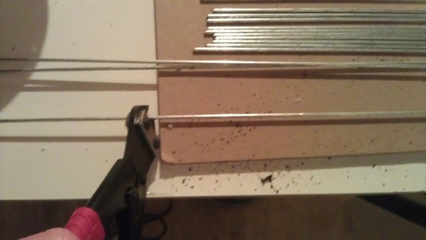
Cut the steel wires to the length of the tube. Standard wire cutters won't work. You'll need the mini bolt cutters. Even with a jig, I find it hard to cut them all to the same length.

Spray them with polyurethane to make them insulating. We want to minimize eddy currents in the wires. 

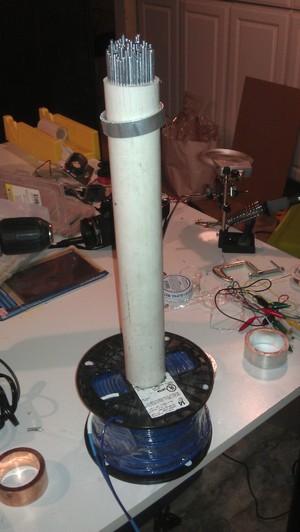
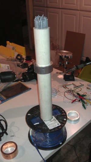
Push them as tightly as you can into the PVC tube. I needed a mallet. The wires aren't held in with glue. Friction seems to be enough.

Step 5: Buy some rings 

Online Metals seems to be a good place to order aluminum or copper tubing. If you go with 1.5 inch PVC then 2.25 inch outside diameter aluminum tubing works well. I found that the 0.125 wall thickness tubing fired the highest, but I also got some thicker 0.25 inch tubing. They will cut to length, and I got 2 inch, 1 inch, and 0.5 inch long pieces. I also bought equivalently sized copper to show that though it is a better conductor, it doesn't fly as high. The copper is expensive, though.

The rings will come with sharp edges. A knife blade will clean them up but a deburring tool works better.

Enjoy!

Wednesday
Apr252012

Improved Ping Pong Ball Vacuum Cannon

I've been planning on improving my Ping Pong Ball Vacuum Cannon for several years, but never really gotten around to it. A couple of months ago, I started on the redesign. Most of the changes were small, but overall they worked out well in a slightly shorter device.

Concept

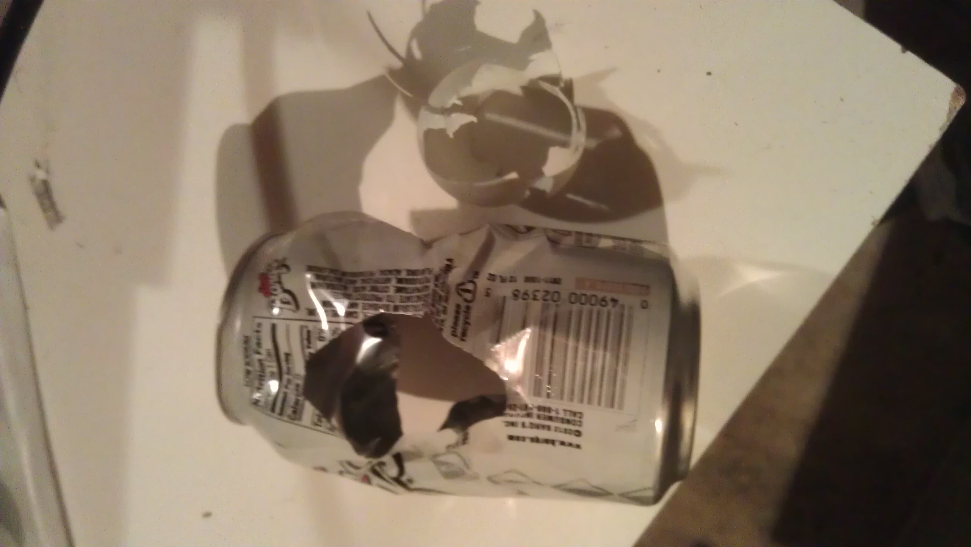
A Ping Pong Ball is placed at the end of aPVC pipe. The ends are covered with mylar. A soda can is placed near the other end. The pipe is evacuated. The far end is ruptured. The Ping Pong ball exits and rips a hole in the can.

Making the Cannon

First, I switched to transparent PVC. The stuff is expensive ($40+) and is not at your ordinary hardware store. Grainger sells it, though, and I picked up this 8 foot section at a local store in Arlington, VA. (I'm on sabbatical this year.) I also got a transparent connector. You can use opaque, but transparent is cool, especially for high speed cameras.

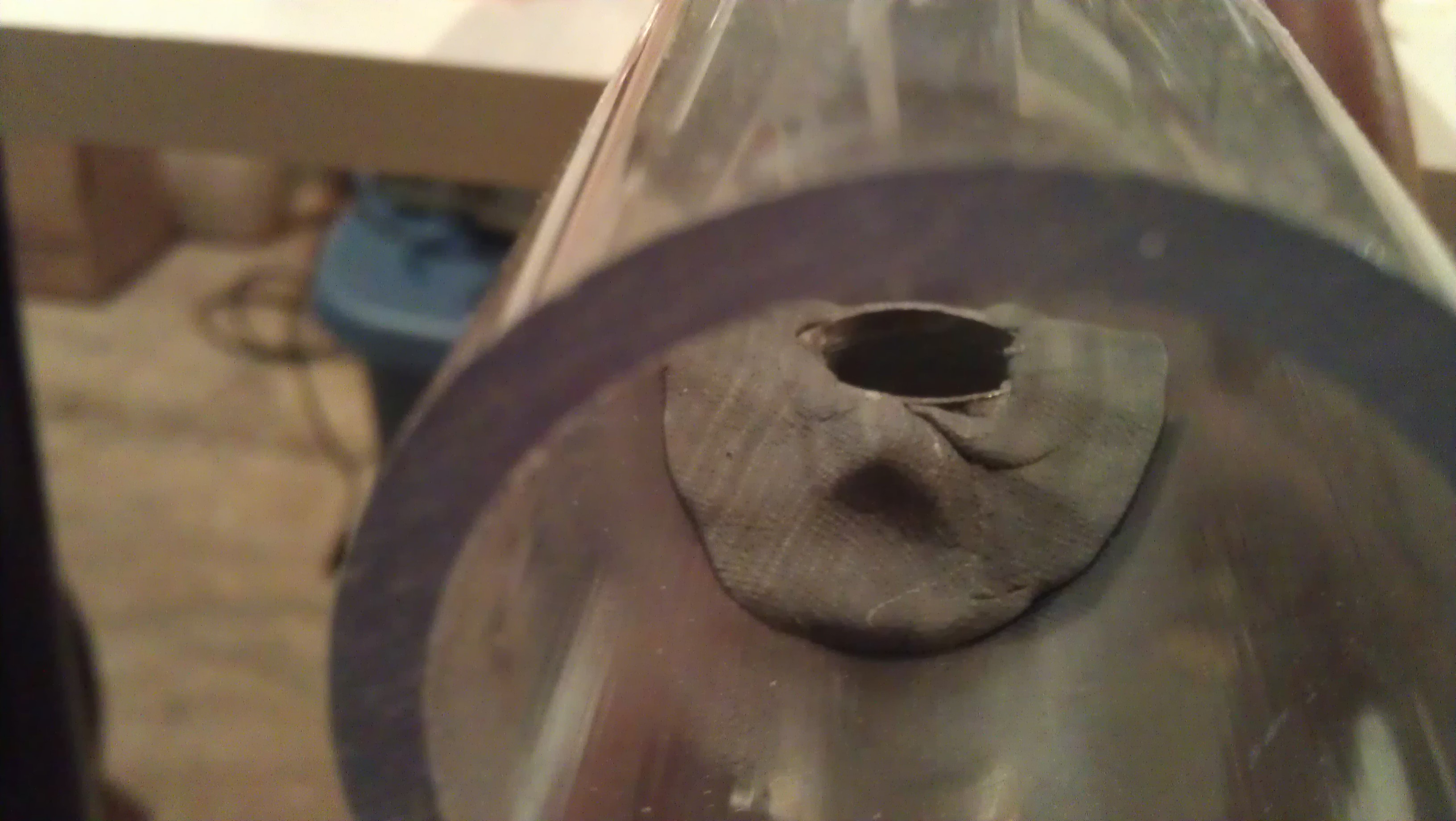
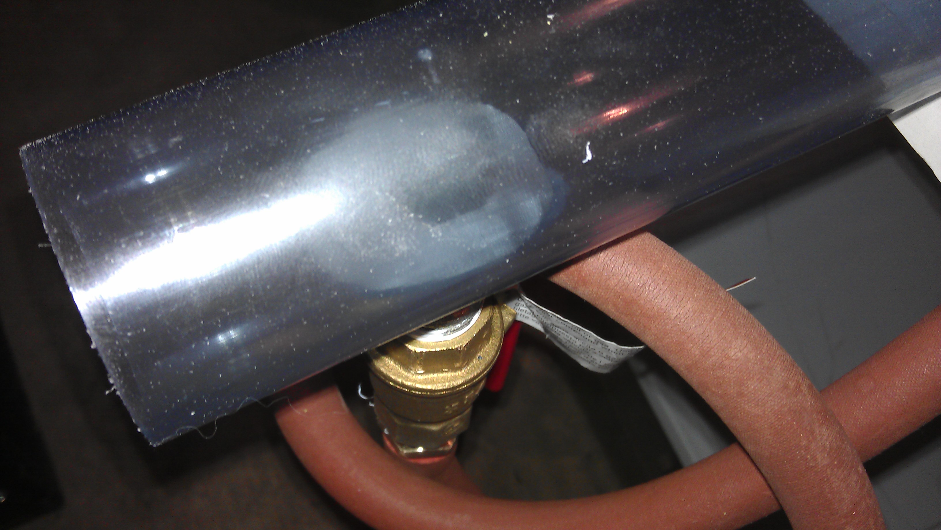
To connect to the vacuum pump, I drilled a hole 4 inches from one end using ???? which does a good job making a clean hole even in PVC. Using a pipe wrench I twisted in a short 3 inch long, 1 inch diameter brass pipe with tapered threaded ends. The pipe itself cut threads in the relatively soft PVC. This seals pretty well but not perfectly. After everything was done (and tested), I kneaded some plumbing epoxy and pressed it around the pipe to give the connection some stability and make a slightly better seal.

I screwed a 1" brass gas valve to the pipe using Teflon tape. I close the valve before firing to protect the pump from in-rushing air. I attached a brass nipple to the other side of the valve also with Teflon Tape.

Tubing and Pump

The red hose is vacuum tubing. I had some given to me, but you can buy it here from Flinn Scientific.

This gets connected to a vacuum pump. I've been using scientific pump but didn't bring it with me from SF. I bought this small pump from Harbor Freight Tools for $150, and it has worked like a champ so far.

I use one star (cheap) standard 40 mm Ping Pong Balls and pieces of emergency blanket (mylar) to seal the ends. I got the idea from folks at BYU, but I see the link is dead. Sigh. What I do is cut a 10 cm x 10 cm square and pull it over the end so it fits smoothly. Here's a picture.

Then I push a PVC connector over to seal. Love this method. It seals better than tape, is much faster to apply, rarely gets sucked into the pipe, and when it does, it doesn't get stuck. 

Can Holder


I used to use a bar clamp to secure a can to a lab jack, but I've upgraded and now have cut a holder.

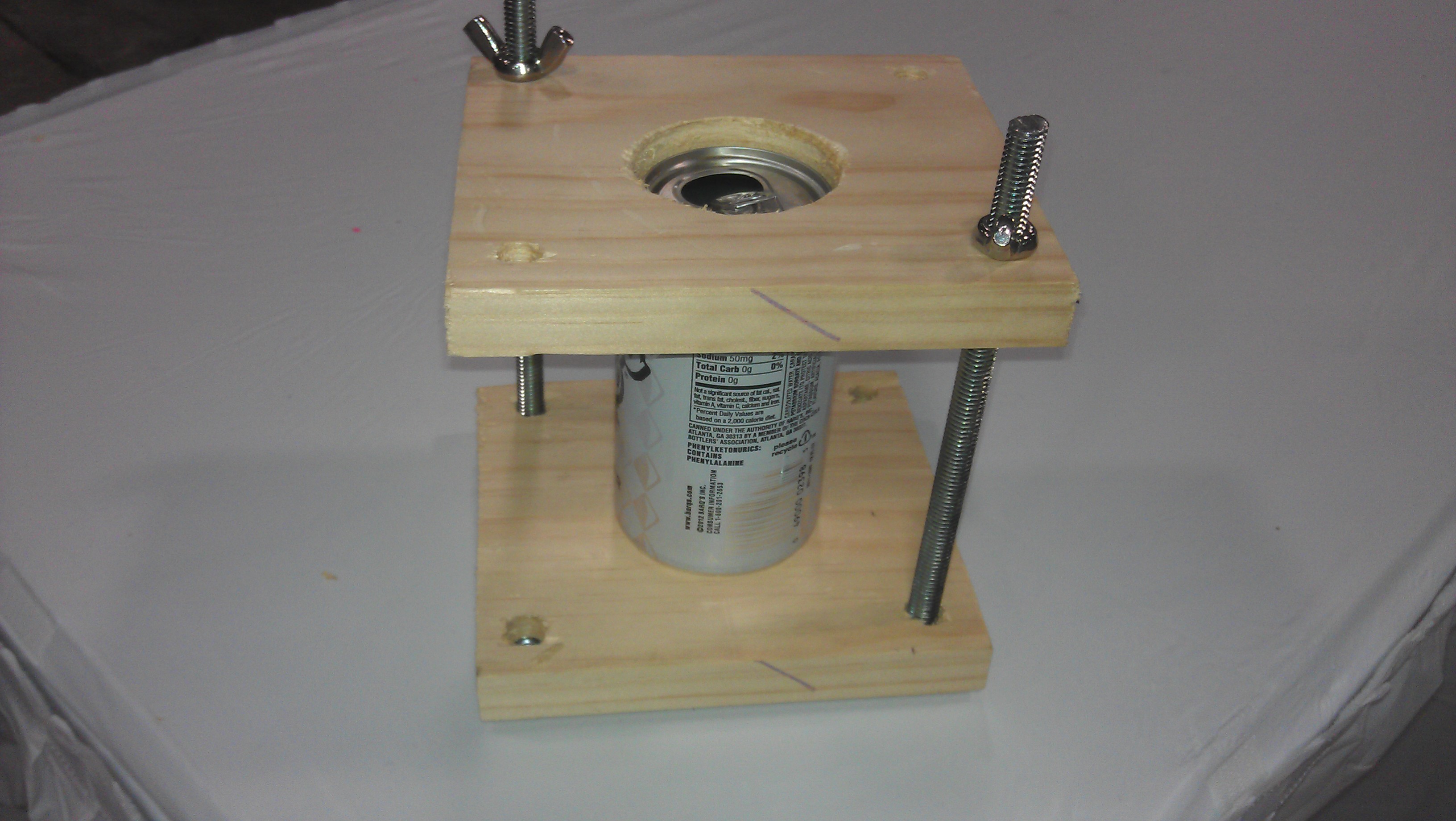
The holder uses the fact that aluminum cans have a slanted top and bottom (a frustum) so that the can can be wedged and held in place.

To make the holder,


  1. Cut two squares of wood approximately 6 inches to a side and 3/4 inch thick. 
  2. Cut a two inch hole in the center of each square using a hole saw. 
  3. Stack the two boards together so that the holes line up as close to perfectly as possible. Clamp together.
  4. Drill two 1/2 inch holes through both boards on opposite corners. I drilled four holes, but I've since discovered that two work just fine and makes it easier to clamp. 
  5. Cut using a hacksaw two pieces of 3/8 inch threaded rod about 7 inches long. 
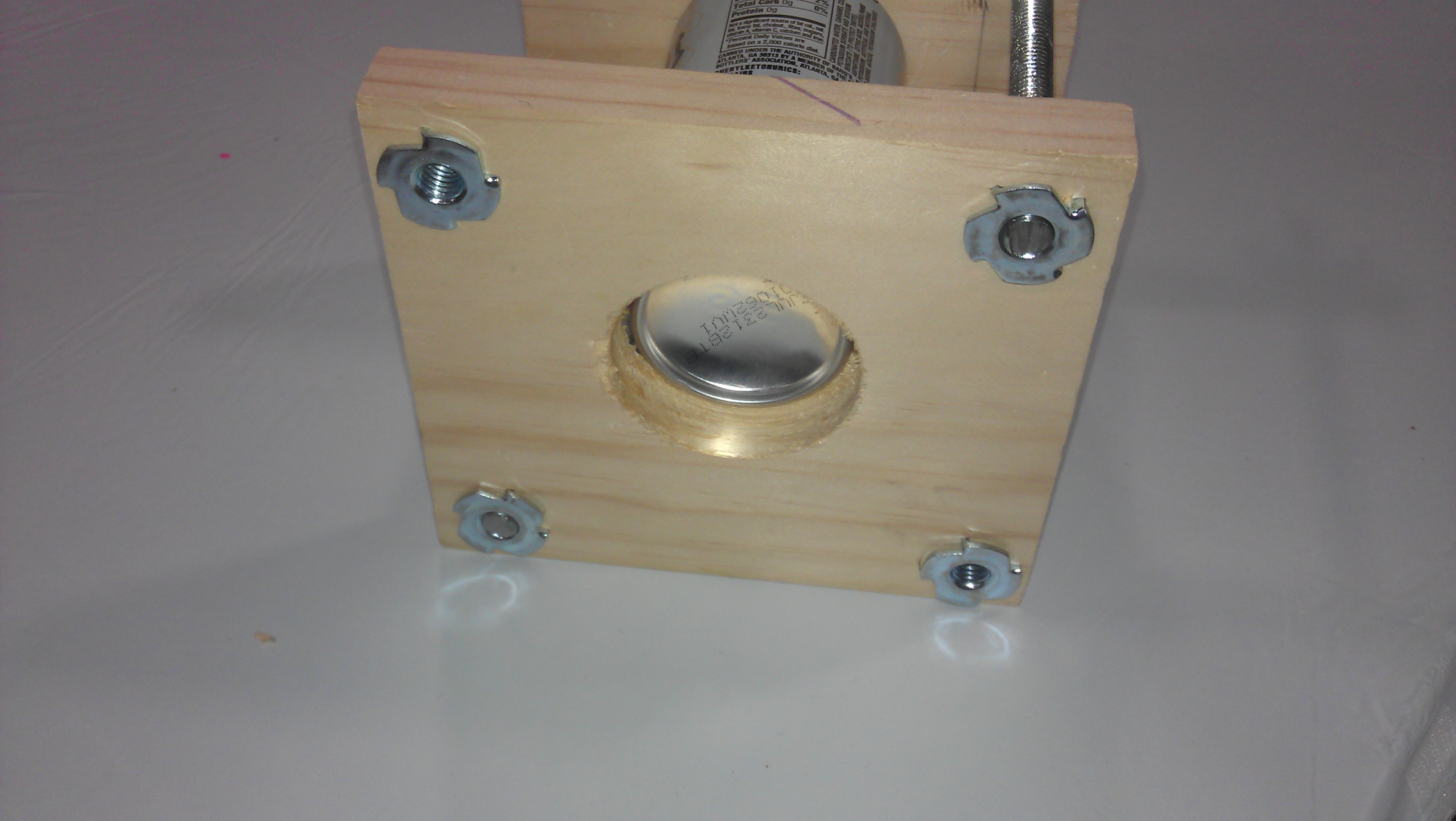
  6. Unclamp the boards. Insert and pound in two 3/8 inch t-nuts in the orientation in the picture. 
  7. Place the can so that the frustums slip into the slots. Tighten with two 3/8 inch wingnuts. 


The fired ball has a lot of energy but not much momentum, so it isn't probably going to knock the holder over or move it far, but metal and pieces of ball can fly after the collision. I put up an explosion shield. It's overkill, though. 

Some people make a holder that holds three cans. The ball tends to pass through the first two cans and get caught by the third. That works well, but I think that it's less dramatic than seeing a single obliterated can. 

Sunday
Apr152012

Optical Siren

For the last several years Ranjit Bhatnagar has made a different musical instrument each day in February. His Optical Siren from 2012's batch caught me attention.

Inspired by Ranjit's siren, I decided to make a larger one for my show. It ended up being fairly straight forward.

The thing in the back is a cordless drill. I cut a circle, using aviation snips, out of a piece of perforated aluminum plate that I bought from Online Metals -- Aluminum 3003-H14 Perforated Sheet Round Hole 0.063" Thick (0.125" dia. holes) 0.1875" stagger. The edges were a bit ragged, even after sanding, so I covered the edges in a couple of layers of duct tape to cushion.

I had to drill out the center a little to put in a screw.

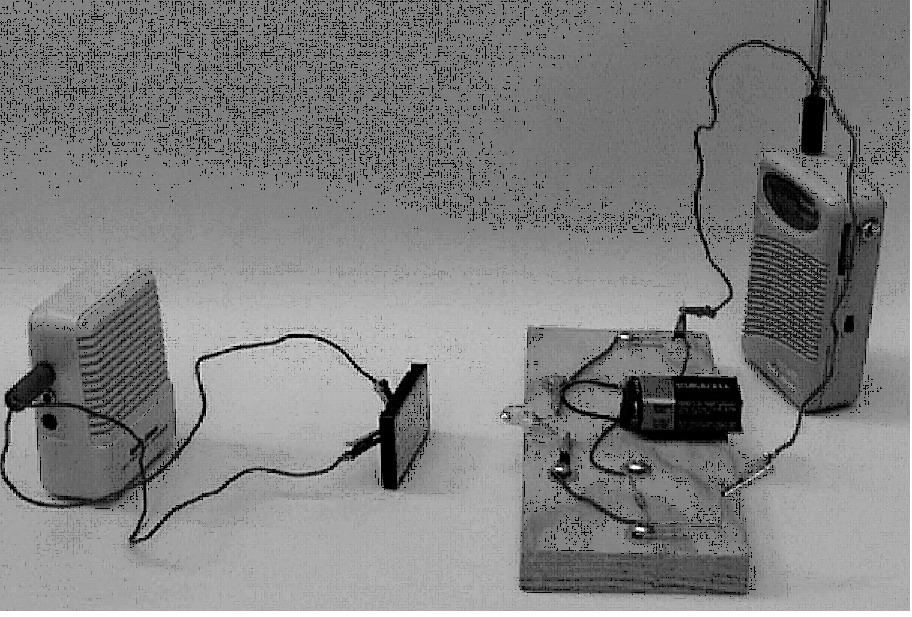
The detector is a optical diode from DigiKey. I got mine from Radio Shack but they don't sell them anymore. I connected it in series to 1/8 inch mini plug (headphone plug) and a 9 V battery. I plugged headphone plug into a small Radio Shack amplifier. You can see this construction as it is similar to the set up for the Communicating with Light arrangement from the Exploratorium.  Remember the photodiode is a diode, and so it will work much better one way than the other. You may have to swap it.  

If you have a fluorescent light in the room, you will hear a buzzing right away. The photodiode works as a switch. The more light that hits it, the lower the resistance, letting more current flow from the battery. Fluorescent lights blink on and off hundreds of times a second, so the amplifier is getting hundreds of pulses of electricity a second. These pulses cause the speaker cone to move out and in, making a compression and an expansion in the air. In a chain reaction or domino way, these compressions and expansions move through the air until they get to your ear where it interprets them as sound.

More compressions per secnod are higher pitches and fewer compressions are lower pitches. Bigger compressiosn or expansions are louder sounds.

The photodiode is so sensitive that even the fluctuation in the intensity of an incandescent light bulb will make a tone.

The main idea though is to create the flashes of light using the spinning disk. Start the drill and place the diode near the spinning disk. When the photodiode is near the center, the pitch is lower. When it is near the edge, it is higher. Why?

Tuesday
May312011

Magnetic Clamp

A few companies sell a magnetic clamp for creating strong magnetic fields. Although the clamps are sturdy and versitile, they are expensive. Often very expensive. I decided to make my own.

I used a Jorgensen wood clamp. The clamps are very strong, and the threaded screw rods allow for very precise adjustment. The magnets are from K&J Magnetics and are 1" x 2" x 0.5" N42 rare earth magnet with (and this is the good thing) counter sunk screws holes. Excellent. Mine took a #10 screw and I used non-magnetic stainless steel, though magnetic steel would have probably been okay. (They are out of stock on this particular magnet, but they expect more and others would work.) 

The key is to drill holes in the wooden handle first, then drive in the screws. 

The idea was to make a pendulum that would show eddy currents. The bar is made of aluminum an 1/8 inch thick and the plates are made from 6 x 12 x 1/8 inch aluminum as well. I cut the slots on a miter saw but I don't recommend that as it was very dangerous, although it works with a carbide blade. I tried a bunch of ways of attaching the plate to the blade, but opted for the clamp which can be changed out the quickest. All the metal was obtained from Online Metals. They cut to order and for cheap.

Monday
May022011

Resonance Glass Breaker

Breaks glass with sound. If you look carefully you can see a broken piece of glass.I built a copy of David Kardelis's glass breaker. <http://www.personal.psu.edu/ref7/apparatus/2006%20competition/kardelis.htm> It breaks pieces of window glass rather than wine glasses. It has some cool advantages over the traditional wine glass breaking with sound. 


  • The neatest thing is that it debunks the idea that only crystal wine glasses can be shattered with sound. 
  • You can see from a distance that the glass is moving and the mode of vibration is really obvious.
  • The breaking frequency is about 34 Hz, nearly outside the range of human hearing. Much more comfortable. 

The glass breaker has three holes. Two supports are added and a strip of window glass is placed on top them.  Sound waves come out of the holes, with the two outside holes being totally out of phase with the center hole. The sound is generated by two speakers that face each other inside of the box.

The inside of David Kardelis's box. I forgot to take a picture before I sealed mine up.

I broke 3 inch by 24 inch strips of window glass at 33.5 Hz.

I've made a few changes to make glass breaking more reliable. 

First, used window is full of micro-fine cracks almost invisible in the glass. These make the glass easy to break. New window glass is much, much harder to break and when it breaks it makes many small pieces. So, when I use new glass, I score it with a glass cutter around the center to help control the breaking.

Second, I bought a good subwoofer amplifier that cost about $100. Mine is a 12 V car amplifier that I run with a computer power supply. You could buy a plate amplifier too. The advantage over a normal receiver is that the output current and voltage have much lower distortion. Subwoofer amps also dissipate heat better. I have burned out a receiver running it for a long time. 

Third, after some excellent advice from fellow physics demonstrators on the mailing list TAP-L, I bought an HP 204C frequency generator. It makes beautiful sine waves. Other frequency generators, especially digital ones, often produce sine waves with jaggeties that seem to interfere with motion. Many of the them make obvious high frequency sound. A picture from HP MemoryI bought mine on Ebay for a good price of about $50. 

With these changes, it breaks glass more reliably than my wine glass breaker without blowing my eardrums out. 

Thursday
Apr282011

Optical Illusion

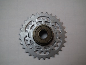
Optical illusions sometimes seem like artifacts of the graphics and drawing, but sometimes normal objects can seem strange. Look at the bicycle gears and hub below.

(Click to enlarge.) Weirdly, they don't look like they both will fit on the same hub. To my eyes, the center hole of the left gear set looks smaller than the center hole of the right gear.

They are of course the same size.


And they both fit on the hub.

This is a physical example of a classic optical illusion where the size of the outside affects your opinion of the inside. The Exploratorium has a good Adobe Shockwave implementation of this effect. <http://www.exploratorium.edu/exhibits/changingill/> The third illusion is pretty much the same as this one.

What suprised me was that the illusion was just as strong in person with real objects as with a graphic on a screen.

Friday
Nov122010

Seeing Where the Microwaves Are

Microwaves are invisible, so you can't see them inside microwave oven, but their presence can be detected with neon lamps. The changing electromagnetic field from the microwaves will make charged particles move, and so the electrons in the metal legs will move creating current. This current makes the lamps glow. I drilled a grid in a piece of 1/4 inch acrylic and slipped the lamps in. I bought the lamps here, but Tom Senior found a better price here. As the platter turns, the lamps light up showing where the microwaves are the strongest.

My grid is based on another group's work.

Wednesday
Nov102010

Vortex Launcher

Steve Spangler Science http://www.stevespanglerscience.com/experiment/00000076 gives a pretty good description on how to make a Vortex Launcher.

Just after Halloween is the time to buy a fog machine. They get very hard to find by spring and you will need to pay a fair bit more to buy one.

Smaller vortex launchers like the Zero Launcher are pretty cool too. http://www.amazon.com/Zero-Toys-Launcher-BLUE/dp/B000FK5JR4

Wednesday
Nov102010

Cup Speaker

There are lots of designs of this, especially ones that use paper plates and suspensions. They all seem much more complicated and finicky for barely any more sound. This http://www.exo.net/~pauld/activities/magnetism/speaker.html from Paul Doherty of the Exploratorium seems to work the best, especially for the novice.

Wednesday
Nov102010

Melting Glass in Your Microwave


My hero Bill Beatty shows how to do this on Vimeo. http://www.metacafe.com/watch/1004040/melt_a_frickn_beer_bottle/ The process is relatively straightforward. Remove the glass plate and rotator from your microwave. Place an empty label-less bottle toward the back of a microwave. Warm the side facing you with a propane or MAPP gas torch, then hone in on an individual spot until it glows red. Close the door and start the microwave.


Sunday
May312009

Hovercraft

The easist solution is to buy the full thing from Pasco, but at $319 it is expensive. A kit that includes everything but the board and air supply is cheaper at $139 but is still costly but not outrageous, especially if you already own a cordless leaf blower. I really recommend this kit.

Building your own is pretty cool too. This set of plans from Bill Beatty (my hero) explains what to do really well and will set you back less than $50 plus the cordless leaf blower.

However, you can combine both of these sets to get a great design for a bit less money. Make the skirt in Bill's plans by using ballistic nylon like Pasco uses. Buy a yard and a half of 330 or 500 denier cordura nylon, like this stuff. Cut it into a circle a couple of inches larger than your hovercraft disk. Hem a hollow edge all the way around the outside of the circle. Follow Bill's advice for cutting circles out of the center. Thread a piece of stiff wire around the seam. By pulling the wire tight, you can keep the skirt attached to the board.

You will need to seal the skirt along the edge. Staples and silicone sealant will probably work, but heavy staples and heavy tape work well too. A rubber bumper like the one Pasco sells used to be available online, but the company where I saw it has gone out of business. (Thanks Steve for telling me!) I'm looking for a replacement.


Friday
May292009

Communicating with Light

Connect an LED to the output of an audio source in such a way that the LED flashes with the source. Then attach an applified speaker to a solar cell and presto you are communicating via light.

<http://www.exploratorium.edu/square_wheels/modulated_led.pdf>


The Exploratorium has a series of books called "Snacks" which explain how to make cool science experiments. Unlike some other books, though, the experiments actually work, and also unlike other some other books their books come with correct explanations of the science behind them. Check out a selection at

http://www.exploratorium.edu/snacks/

You can find the books at most big public libraries. See a list at Amazon here.

Oh, full disclosure, I work/volunteer with the Exploratorium, but I've never worked on a Snack book.

Friday
May292009

Conducting Glass

Tap water conducts electricity, which seems kind of weird since water isn't a metal and has a covalent bond. Of course it conducts because it has ions dissolved in it that can move around and act like the electrons (in a way) as those in a wire. Pure water without ions is a lousy conductor.

Glass is the prototypical example of an insulator. It too is composed mostly of non-metals and has a covalent bond. And like tap water it too has ions. Why doesn't it conduct?

The ions are frozen in place, of course. Let's not argue whether or not room temperature glass is a solid -- suffice it to say that the particles aren't going anywhere fast. On the other hand, if you melt the glass, then the ions can move and then it will conduct electricity.

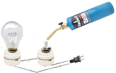
How to do this? Connect two lamp bases in series and then connect them to a wall plug protected by a GFCI. Carefully break the glass globe off a bulb. You will see a plug of glass with two wires coming out of it. The wires are in turn connected to the filament. Clip the wires to the plug of glass. Put an intact bulb in one socket and a the broken bulb in the other socket. Plug them into the wall. Careful, careful. You've got live current here. The GFCI will help but it's not perfect.

Take a torch and heat the glass plug until it glows red/orange. The other bulb will then light up. Notice that the plug will stay molten from the heat running through the wire. Unplug the apparatus. The bulb will go out and the molten glass will cool. If you plug it back in before the glass freezes, the bulb will light up again. If you unplug and wait until the glass is cooler (although still hot enough to burn you) before plugging it back in, then the bulb will not go back on.

Thursday
May282009

Solar Oven

According to solarcooking.org:

Solar cooking is the simplest, safest, most convenient way to cook food without consuming fuels or heating up the kitchen. Many people choose to solar cook for  these reasons. But for hundreds of millions of people around the world who cook over fires fueled by wood or dung, and who walk for miles to collect wood or spend much of their meager incomes on fuel, solar cooking is more than a choice — it is a blessing. For millions of people who lack access to safe drinking water and become sick or die each year from preventable waterborne illnesses, solar water pasteurization is a life-saving skill. The World Health Organization reports that in 23 countries 10% of deaths are due to just two environmental risk factors: unsafe water, including poor sanitation and hygiene; and indoor air pollution due to solid fuel use for cooking.

Plans <http://solarcooking.org/plans/> I like the solar funnel which is really easy to build.

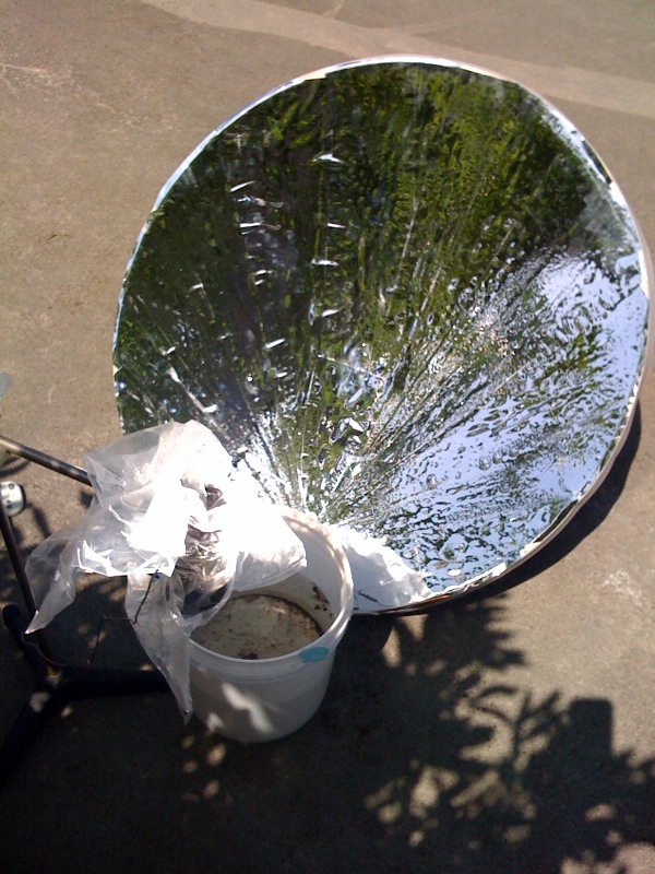
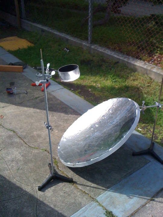
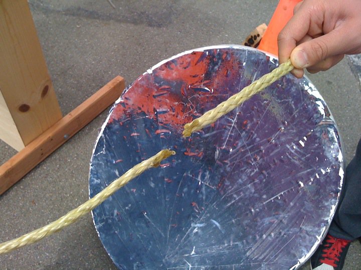
My design is different than any of these and relies on the availabilty of satellite television dishes. In San Francisco, I often see Direct TV and Primestar parabolic dishes being thrown away -- not the receiver mind you -- just the metal dish. I then rubber cement aluminized mylar to the dish. These are amazing. They can get a pint of water to 160 degrees F in about 20 minutes and boil a like amount of water in about 30 minutes.

Wednesday
May272009

Electric Pickle

The electric pickle doesn't really show anything useful, but it's fun. The pickle always glows on only one side, but not always the same one. The glow is clearly from sodium ionization like a sodium lamp. Presumeably the current heats up the pickle and boils water away and at some point ionizes the sodium. It will go for some time but once you unplug the pickle it won't glow again.

This gives a starting explanation, and I always like a link to Hyperphysics <http://hyperphysics.phy-astr.gsu.edu/Hbase/electric/pickle.html>

Some plans here.